- 800-338-0027
- Contact Us
SEARCH Part # or Keyword:
PRODUCT SEARCH:
Enter a keyword or part number in the box below:
 * Part numbers for
 Introduction to Face Driving
- How a Face Driver Works
- How to Select a Face Driver
- Confused? Let Riten Select Your Driver
- Face Driver Application Example
Ever increasing demands on the manufacturer to improve productivity and quality have led to the need for faster machining techniques. Face drivers, along with today’s new high performance equipment, let you maximize your production capabilities for minimal expense.
With a Riten USA Face Driver, the entire workpiece is exposed for machining. Therefore, you are able to machine the entire length of the workpiece in one operation. The elimination of a setup in the production process results in increased accuracy and efficiency. Furthermore, the single axis reference point established by the center point of the face driver allows for a higher concentricity.
The Riten USA Face Driver Line consists of seven hydraulic designs and ten mechanical designs. There is a face driver available for your specific application.
Face Driving Long, Small Diameter Parts
How A Face Driver Works
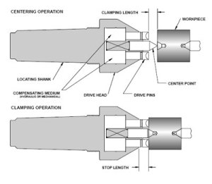
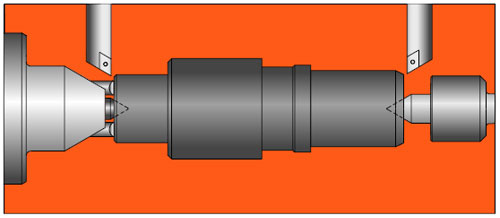
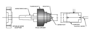
A face driver has two main components, the drive head and the mounting. The mounting locates the driver in the machine with either a morse taper shank mount directly into the machine taper; or a chuck mount chucked between special chuck jaws; or a flange mount bolted to a spindle adapter on the machine spindle. The illustration shows a morse taper shank. The drive head (also known as a carrier body) contains the compensating medium (hydraulic or mechanical); which allows the pins to adjust to variations in the locating face and the spring-loaded center point. Face driving is a simple two step clamping operation, centering followed by clamping. Under tailstock pressure, the workpiece engages the center point which locates the part and provides a consistent axis of rotation. As the tailstock continues to drive the workpiece against the center point, the axial pressure forces the spring-loaded center point back into the carrier body until the drive pins engage the face of the workpiece. Each pin individually compensates for any irregularities in the face until all of the pins are fully engaged. Under the increasing axial load, the drive pins penetrate the workpiece completing the clamping operation, while the center point maintains the axis of rotation.
The compensating medium (either hydraulic or mechanical) in the face driver assures equal penetration of the drive pins despite variations in the surface or in the squareness of the face. Therefore, surface imperfections or out of square saw cuts do not present a problem when face driving.
Five Misconceptions about Face Driving
How to Select a Face Driver
1. Determine the finish diameter (F) of the workpiece at the driving face.
2. Choose the face driver series whose maximum driving diameter (G) is smaller than the finish diameter (F).
3.(G) should be .020 smaller than (F) to allow for clearance.
4.Check the maximum raw stock size (S). (S) should not be more than three times (G) for maximum gripping capabilities. If you require a larger maximum raw bar stock size, please contact Riten technical support m.kirby@riten.com
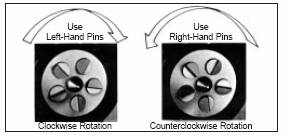
5. Determine the rotation of the headstock to determine drive pin direction. See diagram below:
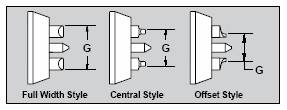
6.Choose the drive pins that allow maximum driving diameter (G). Full width drive pins are the first choice for maximum gripping force.
However, offset, half offset drive pins are also available to meet a broad range of part diameters. See diagram below:
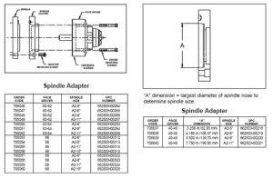
7. Choose the mounting styles (taper
Mount, flange and chuck mount) that are available for each Series of face drivers. If you choose a flange mount and plan to mount the driver directly to the spindle of the machine a spindle adapter will be required. See diagrams below:
FEATURED PRODUCT
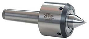
Adjusta-Point Radial Compensating Live Centers
Point can relocated .030” in any direction to compensate for center holes that are not quite on center.